telecaster wiring guide
Telecaster Wiring Guide: A Comprehensive Plan
This guide details Telecaster wiring, covering standard setups, humbucker installations, and troubleshooting.
It utilizes multimeter techniques for accurate pickup lead identification and optimal signal clarity.
Embarking on Telecaster wiring can seem daunting, but understanding the fundamentals unlocks a world of tonal possibilities. This guide demystifies the process, from basic configurations to advanced modifications. Successfully wiring a Telecaster requires careful attention to detail, a solid grasp of electronics, and the right tools.
Proper grounding is paramount for minimizing noise and ensuring a clear, powerful signal. Identifying pickup leads accurately—using a multimeter when necessary—is crucial for correct phasing and output. We’ll explore traditional three-way switching, volume and tone pot wiring, and even adapting humbuckers to the classic Telecaster platform. Let’s begin your journey to a perfectly wired Telecaster!
Understanding Telecaster Electronics
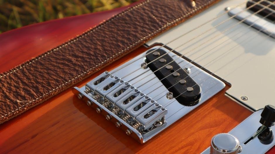
Telecaster circuits are deceptively simple, yet incredibly versatile. At their core, they rely on single-coil pickups, potentiometers (pots) for volume and tone control, and a switch to select between pickups or combine them. The pickups convert string vibration into an electrical signal, which is then shaped by the pots and routed to the output jack.
Understanding the role of each component is key. Pots control signal strength (volume) and frequency response (tone). The switch determines which pickups are active. Grounding is vital for shielding and preventing unwanted noise. Correct wiring ensures proper signal flow and optimal tonal characteristics.
Tools and Materials Needed
Essential tools include a soldering iron, solder, wire strippers, and a multimeter for testing pickup leads and continuity. You’ll also need screwdrivers, pliers, and potentially a drill for control plate modifications. Materials consist of replacement pots (250k or 500k), a switch (3-way or more), output jack, wiring (cloth-covered is preferred), and shielding tape or paint.
Safety glasses are crucial, alongside a well-ventilated workspace. Having extra wire, heat shrink tubing, and a helping hand tool will streamline the process. Don’t forget a wiring diagram specific to your desired configuration!
Basic Telecaster Wiring Diagram (Standard)
A standard Telecaster circuit features two single-coil pickups, a volume control, a tone control, a three-way switch, and an output jack. The bridge pickup’s hot lead connects to the switch’s first lug, while the neck pickup’s hot lead goes to the switch’s second lug.
The switch’s common lug feeds the volume pot, which then connects to the tone pot and finally to the output jack. Proper grounding is vital; all pots and the switch should be connected to a common ground point, typically the back of the volume pot.
Identifying Pickup Leads: The Multimeter Method
Accurate pickup lead identification is crucial for correct wiring. Using a multimeter set to 20K ohms, measure resistance between wire pairs. White/black typically form one coil (6-8K ohms), and red/green the other. If no reading, test white/red against black/green.
Confirm series wiring by probing white, tying red and black, and connecting to green; double the resistance indicates correct configuration. A bare wire always grounds to the circuit’s ground point.
Measuring Coil Resistance

Begin by setting your multimeter to the 20K ohm range. This setting is ideal for accurately measuring the resistance of typical Telecaster pickup coils. Start by testing the white wire against the black wire; a reading between 6-8K ohms suggests you’ve identified one coil.
Next, measure the red wire against the green wire. You should obtain a similar resistance value, confirming the second coil. Consistent readings validate your initial coil identification.
Determining Series vs. Parallel Wiring
To identify the series configuration, place one multimeter probe on the white wire. Then, temporarily connect the black and red wires together. Place the second probe on the green wire. A resistance reading of 12-16K ohms indicates a series wiring scheme.
If the reading is half that value, disconnect the black and red wires. Instead, connect the black and green wires together, and remeasure with probes on the white and red wires. This confirms parallel wiring.
Confirming Lead Identification (White/Black & Red/Green)
Begin by setting your multimeter to the 20K ohm range. Measure the resistance between the white and black wires; a reading of 6-8K ohms suggests they represent one coil. Subsequently, measure between the red and green wires – you should obtain a similar resistance value.
If no reading appears on either of these tests, switch probes to measure between the white and red wires, and then the black and green wires. This confirms proper lead identification for accurate wiring.
Wiring a 3-Way Switch (Traditional Telecaster)
The three-way switch manages pickup selection in a classic Telecaster. It features hot, ground, and output connections crucial for proper function. Understanding the switch’s lug configuration is key; typically, the common lug connects to the output jack.
The remaining lugs receive hot leads from the pickups. Careful attention to wiring ensures seamless transitions between neck, bridge, and combined pickup settings, delivering the iconic Telecaster tones.
Hot, Ground, and Output Connections
Establishing correct hot, ground, and output connections is fundamental. The “hot” lead carries the signal from each pickup to the switch. Grounding, vital for noise reduction, connects pickup casings and the control cavity to the volume pot’s back.
The output connection, typically to the jack, transmits the final signal. Proper soldering and insulation prevent shorts and ensure a clean, strong signal path, maximizing tonal clarity and minimizing unwanted interference.
Switch Lug Configuration Explained
A traditional Telecaster 3-way switch utilizes three lugs per side. The common lug connects to the output jack, receiving the signal after selection. The other two lugs on each side correspond to the neck and bridge pickup’s hot wires, respectively.
Correct wiring dictates which pickup is active in each switch position. Misconfiguration leads to incorrect signal routing or a non-functional circuit. Careful attention to the diagram is crucial for proper operation and tonal control.
Wiring Pots (Volume and Tone)
Volume and tone potentiometers are central to shaping your Telecaster’s sound. The volume pot controls signal amplitude, while the tone pot filters high frequencies. Proper wiring ensures smooth operation and minimal noise.
Typically, 250k or 500k pots are used, depending on pickup output. Grounding is vital; the pot casings connect to the circuit’s ground, reducing hum. Accurate lug connections are essential for correct functionality and tonal characteristics.
Volume Potentiometer Wiring
The volume pot receives the hot output from the pickup selector switch. This hot signal connects to the center lug of the potentiometer. The two outer lugs connect to ground and the output to the tone pot.
Ensure a solid ground connection to the pot casing to minimize noise. Proper soldering is crucial for a reliable signal path. The volume pot’s value (250k or 500k) impacts the overall tone and brightness of your Telecaster.
Tone Potentiometer Wiring
The tone pot controls high-frequency roll-off, shaping your Telecaster’s sound. It receives its input from the volume pot’s output lug. A capacitor, typically 0.047uF, connects between the tone pot’s center lug and ground, creating the tone-shaping circuit.

The remaining tone pot lug connects to ground. Like the volume pot, a secure ground connection to the casing is vital. Experiment with different capacitor values to fine-tune the tone control’s effect.
Connecting Volume and Tone Pots (Ground Circuit)
A crucial element is linking the volume and tone pots to establish a robust ground circuit. This connection typically occurs between lug one of the volume pot and lug three of the tone pot, ensuring signal integrity.
This interlinking minimizes noise and hum, providing a cleaner output. Remember to also ground the pot casings to the circuit, often via the control plate or back of the potentiometers, completing the ground path.
Grounding Scheme: Ensuring a Quiet Signal
Effective grounding is paramount for a noise-free Telecaster. Begin by soldering the bare wire from each pickup directly to the volume potentiometer, creating a central ground point.
Consider grounding the control plate to the circuit, further reducing interference. Ensure all connections are solid and free of cold solder joints. A well-executed grounding scheme minimizes hum and maximizes signal clarity, delivering a professional sound.
Bare Wire Grounding to Volume Pot
The bare wire from each pickup acts as a crucial ground connection. Solder this wire directly to the back of the volume potentiometer, establishing a common ground point for the entire circuit.
This connection minimizes noise and hum by providing a low-impedance path for unwanted signals. Ensure a secure solder joint for optimal conductivity. This simple step significantly improves the overall signal quality and reduces interference within your Telecaster.
Grounding Considerations for Control Plates

When using a control plate, proper grounding is paramount. Connect the control plate directly to the volume potentiometer’s casing, creating a solid ground link. This prevents ground loops and minimizes unwanted noise.
Use a short, direct wire for this connection, avoiding unnecessary length. Consider adding a copper foil shield to the control cavity for enhanced shielding against electromagnetic interference, further improving signal clarity and reducing hum within your Telecaster’s circuitry.
Humbucker Installation in a Telecaster (No Coil Split)
Installing humbuckers requires adapting their wiring to the Telecaster’s existing controls. Typically, the black wire serves as the ground, while the green wire connects to the switch. However, Artec pickups may have swapped colors, mirroring Seymour Duncan’s layouts.
Tie the red and white wires together, insulating the connection. The bare wire, always a ground, joins the black wire at the volume pot. This configuration ensures compatibility and proper functionality within the Telecaster’s circuit.
Adapting Humbucker Wiring to Telecaster Controls
Humbuckers necessitate a modified approach to Telecaster wiring. The standard setup involves treating the black wire as the ground, connecting it alongside the pickup’s bare wire to the volume potentiometer. The green wire is routed to the three-way switch for signal selection.

Red and white leads are joined, effectively creating the hot connection. Ensure proper insulation to prevent shorts. This adaptation allows seamless integration of higher-output humbuckers into the traditional Telecaster control scheme, maintaining functionality.
Identifying Humbucker Leads (Black as Ground, Green to Switch)
Artec rail humbuckers generally follow a color-coding convention: black serves as the ground, connecting to the volume pot’s ground lug alongside the bare wire. The green wire is designated for the switch, carrying the signal to the output jack. Red and white wires represent the coil leads.
Confirming this scheme is crucial; though Seymour Duncan’s diagrams offer a similar layout with swapped colors, verifying with a multimeter ensures correct wiring and optimal performance. Proper identification prevents phase issues and ensures a clear, powerful tone.
Troubleshooting Common Telecaster Wiring Issues

Common issues include unwanted hum and signal loss. Hum often stems from inadequate grounding; ensure bare wires connect securely to the volume pot and control plate. Signal loss can result from cold solder joints or incorrect wiring configurations, particularly with the switch or potentiometers.
Carefully review your wiring diagram, checking each connection. Utilize a multimeter to verify continuity and identify breaks in the signal path. Addressing these issues systematically will restore a quiet, strong output.
Hum and Noise Reduction Techniques
Effective grounding is paramount for minimizing hum. Connect all ground points – pickup bases, control cavity, bridge – to the volume potentiometer’s casing. Shielding the control cavity with conductive paint or copper foil further reduces interference.
High-quality shielded cable minimizes noise pickup. Ensure proper wire routing, keeping signal wires away from potential noise sources. A dedicated ground wire running throughout the circuit enhances overall noise rejection, resulting in a cleaner signal.
Signal Loss and Weak Output
Weak output often stems from incorrect wiring or faulty components. Verify all connections are secure and solder joints are clean. Check potentiometer values; incorrect resistance can significantly reduce signal strength. Inspect pickup height – too low diminishes output.
Ensure proper grounding, as a poor ground can cause signal loss. Use a multimeter to confirm continuity throughout the circuit. Replace any damaged or corroded components, like pots or the output jack, to restore optimal signal flow and volume.
Advanced Wiring Modifications
Explore series/parallel switching for tonal versatility. This alters pickup phasing, offering thicker or brighter sounds. Push/pull pots enable coil splitting, transforming humbuckers into single-coils, expanding sonic options.
Consider a belly-up switch for additional pickup combinations. Carefully plan modifications, referencing detailed wiring diagrams. Ensure all components are compatible and properly grounded to avoid unwanted noise or signal loss. Experimentation unlocks unique Telecaster tones!
Series/Parallel Switching Options
Series wiring doubles pickup output and resistance, creating a thicker, warmer tone with increased sustain. Parallel wiring maintains a brighter sound with reduced output, offering clarity and sparkle.
Implementing a switch allows toggling between these modes. This requires careful wiring, often utilizing a DPDT switch. Series is ideal for rhythm playing, while parallel excels in lead tones. Experiment to discover your preferred settings!
Adding a Push/Pull Pot for Coil Splitting (If Applicable)
Coil splitting transforms humbuckers into single-coils, expanding tonal versatility. A push/pull potentiometer replaces a standard pot, adding a switch function when pulled.
Wiring involves connecting the coil split wires to the pot’s switch terminals. This allows selecting either the full humbucker or a single coil. Ensure proper grounding to avoid noise. It’s a fantastic modification for Telecasters seeking increased sonic options!
Resources and Further Learning
For detailed diagrams, Seymour Duncan’s website (https://www.seymourduncan.com/) offers a vast library of Telecaster wiring schemes, invaluable for complex modifications.
Online communities, like Telecaster Discussion Page Forum, provide a platform to connect with experienced builders, ask questions, and share knowledge. These resources are essential for navigating the intricacies of Telecaster electronics and achieving professional results.
Seymour Duncan Wiring Diagrams
Seymour Duncan’s website (https://www.seymourduncan.com/) provides extensive, color-coded wiring diagrams for various Telecaster configurations. These diagrams are particularly helpful when dealing with pickups lacking included schematics, like the Artec rail humbuckers.
Note potential color swaps; Artec pickups may reverse the traditional green/black ground scheme. Carefully compare the diagram to your pickup’s leads, utilizing a multimeter to confirm proper identification before soldering, ensuring a functional and noise-free circuit.
Online Telecaster Wiring Communities
Numerous online forums and communities cater specifically to Telecaster enthusiasts and wiring modifications. These platforms, like the Telecaster Discussion Page (https://www.tdpri.com/), offer invaluable support, troubleshooting advice, and shared experiences from seasoned builders.
These communities are excellent resources for deciphering complex wiring schemes, particularly the often-confusing GB wiring, and finding solutions to unique wiring challenges. Don’t hesitate to ask questions and learn from others!